In precision manufacturing, tolerances are more than numbers on a blueprint; they are the silent architects that shape the functionality, reliability, and cost of a product. Imagine assembling a wristwatch: even a 0.02mm mismatch between gears could render the entire mechanism useless. For industrial clients, product designers, and engineers involved in CNC machining, mastering this balance between precision and practicality isn’t just a skill—it’s a cornerstone of successful production. This guide unpacks the nuances of tolerances, from foundational concepts to real-world application strategies.
The Basics of Tolerances in CNC Machining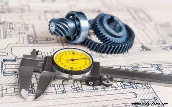
At its core, a tolerance in CNC machining defines the permissible range between the maximum and minimum dimensions of a part. While computer numerical control systems operate with remarkable accuracy, variables like tool wear, material expansion, and machine vibration make absolute precision unattainable. Tolerances bridge this gap, ensuring parts remain functional despite these inevitable variations.
Consider a simple bracket designed to secure electrical components. If the blueprint specifies a 50mm length with a ±0.2mm tolerance, any bracket measuring between 49.8mm and 50.2mm will work. This flexibility acknowledges that even state-of-the-art CNC machines can’t replicate dimensions with atomic precision—nor should they, unless necessary. Think of tolerances as the manufacturing equivalent of a tailor allowing extra fabric for a comfortable fit, rather than stitching a suit to exact millimeter measurements that would tear with movement.
Common Types of Tolerances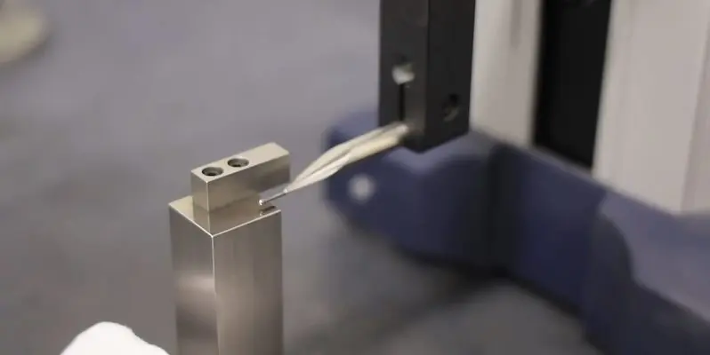
Dimensional Tolerances
These specify allowable deviations from linear measurements like length, width, or diameter. They’re expressed either as bilateral tolerances (e.g., 25mm ±0.05mm) where variation is permitted in both directions, or unilateral tolerances (e.g., 10mm +0.03/-0mm) where deviation is restricted to one side.
A practical example: automotive brake caliper pins require a unilateral tolerance. The pin must fit snugly into its housing to prevent fluid leaks, so designers specify 12mm +0.01/-0mm. This ensures the pin never shrinks below 12mm (which could cause looseness) but allows a tiny 0.01mm expansion that won’t compromise the seal.
Geometric Tolerances (GD&T)
Unlike dimensional tolerances that focus on size, GD&T controls the shape and positional relationships between features. This system uses symbols to define parameters like flatness (how uniformly flat a surface must be) or positional tolerance (how accurately a hole must align with other components).
In the renewable energy sector, wind turbine hub assemblies rely heavily on GD&T. Each bolt hole in the hub must align within 0.05mm of its designated position relative to neighboring holes. If misaligned, the uneven stress distribution could cause premature fatigue in the turbine’s structure—a failure that could cost millions in repairs. GD&T here acts like a 3D map, ensuring every feature interacts harmoniously.
The Impact of Tolerances on the Final Product
Functionality
Tolerances directly dictate how well parts interact. In hydraulic systems, for instance, a piston with a tolerance of ±0.03mm must slide within a cylinder with matching precision. Too loose, and hydraulic fluid leaks; too tight, and friction generates heat that degrades seals.
Medical device manufacturers face even stricter demands. A catheter’s internal lumen (the hollow channel) requires tolerances as tight as ±0.005mm to ensure consistent drug flow rates. A 0.01mm variance could double or halve the dosage—potentially life-threatening outcomes that highlight why certain applications demand uncompromising precision.
Cost and Lead Time
Tighter tolerances create a ripple effect on production costs. A part requiring ±0.01mm tolerance might take 30% longer to machine than one with ±0.1mm, as operators must slow feed rates and perform more frequent tool calibrations. Inspection costs also rise: while a ±0.1mm part can be checked with calipers, ±0.01mm precision demands coordinate measuring machines (CMMs) that cost upwards of $50,000.
A case study illustrates this: a furniture manufacturer redesigned a chair bracket from ±0.05mm to ±0.2mm tolerance. The change reduced machining time by 22% and cut inspection costs by 40%—all without affecting structural integrity, since the bracket’s function (supporting weight) didn’t require pinpoint precision.
Material Considerations
Material properties complicate tolerance selection. Plastics like ABS expand up to 0.02mm per meter for every 1°C temperature change, so outdoor components need looser tolerances to accommodate thermal movement. Metals behave differently: aluminum’s high machinability allows tighter tolerances than cast iron, which tends to chip and deform during cutting.
Aerospace engineers address this by specifying tolerances based on operating conditions. Jet engine components, which experience temperatures from -50°C to 1,000°C, use Inconel alloys with low thermal expansion—and still require tolerances that account for 0.01mm per meter expansion to prevent jamming at altitude.
How to Select the Right Tolerances
Map the Assembly Ecosystem
Start by analyzing how the part interacts with others. For moving parts (gears, bearings), focus on clearance and friction: a gear tooth with ±0.02mm tolerance prevents binding, while a bearing race might need ±0.008mm to maintain smooth rotation. Static parts (mounting plates, covers) often function well with ±0.1mm or looser tolerances.
Collaborate with Machinists Early
Experienced CNC shops bring invaluable perspective. A designer specifying ±0.005mm for a large aluminum plate might not realize the material warps slightly after machining—a phenomenon machinists know can be mitigated by adjusting tolerances to ±0.01mm and using stress-relief annealing. This collaboration avoids redesigns and reduces lead times.
Test with Prototypes
3D printing prototypes with intentional tolerance variations can reveal non-obvious needs. A robotics company found their gripper fingers worked best with ±0.08mm tolerance after testing: ±0.05mm caused them to grip too tightly, damaging parts, while ±0.1mm led to slippage. Prototyping turned theoretical tolerances into practical solutions.
Conclusion
CNC machining tolerances are the intersection of design intent and manufacturing reality. They demand engineers ask not “how precise can we get?” but “how precise do we need to be?” By balancing functional requirements with material behavior and production capabilities, designers create parts that perform reliably without inflating costs. Remember: the best tolerances aren’t the tightest—they’re the ones that make your product work, last, and remain affordable to produce.