
A tolerance defines how much a finished dimension is allowed to deviate from the nominal value on your drawing. Get it wrong and you either pay for precision you don’t need, or receive parts that don’t assemble. This guide gives you the ISO 2768 reference tables, a process-based selection method, and the tradeoffs between milling and turning for tolerance-critical features.
What a Tolerance Actually Controls
A dimension of Ø10.00 mm with a tolerance of ±0.05 mm means any part measuring between 9.95 mm and 10.05 mm passes inspection. Two tolerance types cover different failure modes:
- Dimensional tolerance — controls size: length, diameter, depth.
- Geometric tolerance (GD&T) — controls shape and position: flatness, perpendicularity, position, concentricity.
A part can pass its dimensional tolerance and still fail geometric tolerance — for example, a shaft can be the correct diameter everywhere but still be bent (fail straightness). Both must be specified for features that mate with other parts.
ISO 2768 General Tolerance Chart
When a dimension on your drawing has no individual tolerance called out, ISO 2768-1 sets the default. Specify the class (e.g., “ISO 2768-m”) in your drawing’s title block.
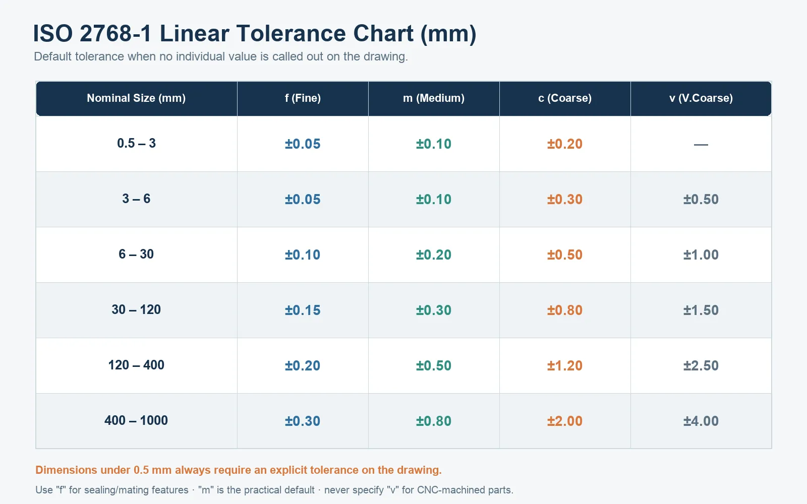
ISO 2768-1: Linear Dimensions (mm)
| Nominal size range | f (fine) | m (medium) | c (coarse) | v (very coarse) |
|---|---|---|---|---|
| 0.5 to 3 | ±0.05 | ±0.10 | ±0.20 | — |
| Over 3 to 6 | ±0.05 | ±0.10 | ±0.30 | ±0.50 |
| Over 6 to 30 | ±0.10 | ±0.20 | ±0.50 | ±1.00 |
| Over 30 to 120 | ±0.15 | ±0.30 | ±0.80 | ±1.50 |
| Over 120 to 400 | ±0.20 | ±0.50 | ±1.20 | ±2.50 |
| Over 400 to 1000 | ±0.30 | ±0.80 | ±2.00 | ±4.00 |
| Over 1000 to 2000 | ±0.50 | ±1.20 | ±3.00 | ±6.00 |
Dimensions under 0.5 mm must always carry an explicit tolerance on the drawing — ISO 2768 does not cover them.
ISO 2768-1: Angular Tolerances
| Shortest side length (mm) | f & m | c | v |
|---|---|---|---|
| Up to 10 | ±1° | ±1°30′ | ±3° |
| Over 10 to 50 | ±0°30′ | ±1° | ±2° |
| Over 50 to 120 | ±0°20′ | ±0°30′ | ±1° |
| Over 120 to 400 | ±0°10′ | ±0°15′ | ±0°30′ |
ISO 2768-2: Geometric Tolerances (Flatness & Straightness, mm)
| Nominal length | H (high) | K (medium) | L (low) |
|---|---|---|---|
| Up to 10 | 0.02 | 0.05 | 0.10 |
| Over 10 to 30 | 0.05 | 0.10 | 0.20 |
| Over 30 to 100 | 0.10 | 0.20 | 0.40 |
| Over 100 to 300 | 0.20 | 0.40 | 0.80 |
A drawing callout combining both parts reads “ISO 2768-mK” — medium linear tolerance, medium geometric tolerance.
Which Class to Specify
ISO 2768-m is the practical default for aluminum and steel machined parts — brackets, housings, non-mating covers. ISO 2768-f is for features that seal or locate against another part: bearing bores, sealing faces, dowel holes.
Do not specify “v” (very coarse) for CNC-milled or turned features — it belongs to sheet metal, weldments, and rough castings, not machined parts.
GD&T: When Position Matters More Than Size
If a feature’s function depends on where it sits relative to other features — not just its own size — dimensional tolerance is the wrong tool. Use GD&T symbols instead:
| Symbol | Controls | Typical use |
|---|---|---|
| ⏥ Flatness | Deviation of a surface from a perfect plane | Sealing faces, mounting surfaces |
| ⊥ Perpendicularity | Angle between two features | Shaft shoulders, mounting bosses |
| ⌭ Position (true position) | Location of a hole/feature relative to a datum | Bolt patterns, dowel holes |
| ◎ Concentricity | Axis alignment of two circular features | Stepped shafts, bearing seats |
| ⌰ Runout | Surface deviation during rotation | Rotating shafts, spindles |
A bolt-hole pattern with a tight positional tolerance and a loose diameter tolerance is common: the hole size can vary slightly, but its location relative to the pattern cannot.
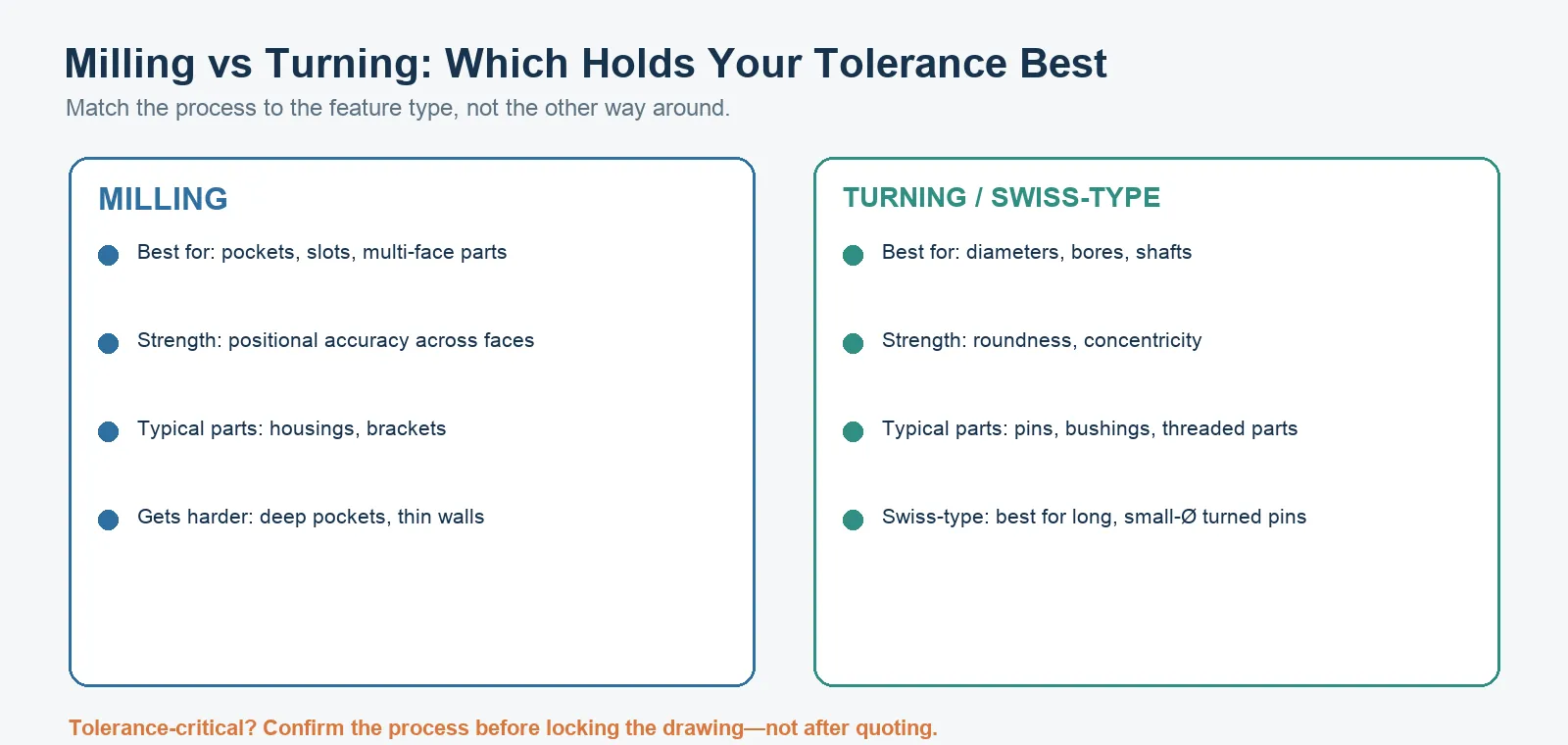
Milling vs. Turning: What Each Process Holds Best
The process you specify affects which tolerances are practical to hit cost-effectively.
| Fresado | Turning / Swiss-type | |
|---|---|---|
| Best suited to | Pockets, slots, multi-face features, bolt patterns | Diameters, bores, shafts, concentric features |
| Tolerance strength | Positional accuracy across multiple faces | Roundness, concentricity, diameter control |
| Gets harder at | Deep pockets, thin walls, long-reach small features | Non-round features, very long L/D ratios without support |
| Typical parts | Housings, brackets, multi-axis components | Pins, bushings, shafts, threaded parts |
For long, small-diameter turned parts (pins, shafts under roughly Ø6 mm), Swiss-type turning holds tighter roundness and straightness over length than a standard lathe, because the material is guide-bushing supported near the cutting point.
What Drives Machining Cost as Tolerance Tightens
Tighter tolerance raises cost through three mechanisms, not one flat multiplier:
- Slower cutting parameters — reduced feed rate and depth of cut to control tool deflection and heat.
- More inspection — calipers are enough for ISO 2768-m; features tighter than roughly ±0.02 mm typically require a CMM.
- Higher scrap risk — tighter tolerance leaves less room for tool wear drift across a batch, so more in-process checks are needed.
The fix is not avoiding tight tolerances — it’s applying them only where the feature’s function requires them, and leaving the rest at the ISO 2768 default.
A Practical Decision Path
Before specifying a tolerance tighter than ISO 2768 default, check:
- Does the feature mate, seal, or locate against another part? If not, the ISO default is enough.
- Is a coating or plating applied afterward? State whether the tolerance applies before or after finishing — anodizing and plating add measurable thickness.
- Is position more important than size? Use GD&T rather than tightening every linear dimension.
- What’s the material? Metals hold tighter tolerances more predictably than plastics, which are more sensitive to heat and machining stress.
How JXD Handles Tolerance-Critical Parts
For features called out on the drawing, JXD confirms the required tolerance class and inspection method before quoting — including whether GD&T callouts require CMM measurement or can be verified with standard gauges. First-article inspection reports and CMM data are available when specified in the RFQ; see the first CNC order checklist for what to include on your purchase order.
Material and process selection also affects what’s achievable: our CNC machining service overview covers milling, turning, and Swiss-type capability, and the China CNC outsourcing guide covers what to include in your RFQ package alongside tolerance callouts.
For plastic parts specifically, thermal sensitivity affects tolerance choice more than machine capability — see our material selection resources for grade-specific behavior.
FAQ
What’s the difference between ISO 2768-1 and ISO 2768-2? ISO 2768-1 covers linear and angular dimensions. ISO 2768-2 covers geometric tolerances like flatness and perpendicularity. A drawing can reference both, e.g., “ISO 2768-mK.”
Do threads follow ISO 2768 tolerances? No. Threads follow their own standards (ISO 965-1 for metric threads). Always call out thread tolerance class separately on the drawing.
Can I mix tolerance classes on one drawing? Yes. Set ISO 2768-m as the general tolerance, then call out tighter values only on the specific dimensions that require them. This keeps cost down by adding precision only where function requires it.
Is turning always more precise than milling? Not universally — each process is stronger at different feature types. Turning typically holds tighter roundness and diameter control on cylindrical features; milling is stronger for positional accuracy across multiple faces. Match the process to the feature, not the other way around.
Send Your Drawing for Review
Upload your STEP file and 2D drawing with tolerance callouts, and JXD’s engineering team will confirm which tolerances are achievable at reasonable cost before you commit to a production run.
Get a Tolerance & DFM Review →
—
 Spanish
  English
  German
  Italian
  Russian
  Turkish
  French
  Portuguese