An aerospace bracket sits bolted to an electro-dynamic shaker table, undergoing a high-frequency vibration test intended to simulate 10,000 flight hours of aggressive aerodynamic buffeting. At cycle 8,400, a microscopic fatigue crack initiates at a 0.2mm subsurface gas pore. Within milliseconds, the crack propagates through the cross-section, and the bracket violently shears in half, sending shrapnel across the test cell. We have seen too many startups scrap their first batch because they designed a load-bearing component, looked at the unit cost, and selected A356-T6 cast aluminum to save money. Weeks later, they watch their mission-critical assemblies disintegrate on the test stand.
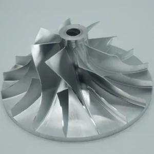
The debate of billet aluminum vs cast is not an academic exercise for finite element analysis (FEA) theorists; it is the physical difference between a part that survives a 10G shock load and a part that causes a catastrophic system failure. Over the past 15 years, the engineering team at JXD Machining has built a core business out of rescuing failed casting designs. Senior mechanical engineers routinely send over 3D models of shattered cast components, desperate for a permanent solution. The fix is always identical: discard the porous casting, secure a solid block of aerospace-grade 7075-T6 or 6061-T6, and aggressively mill it to completion on our fleet of 29 Haas and Taikan machining centers. Billet parts machining permanently eliminates the micro-porosity variables that plague foundries, resulting in components with predictable, isotropic fatigue strength.
The Hidden Danger of Cast Aluminum
The foundational flaw of cast aluminum lies in the physics of solidification. Whether a foundry utilizes high-pressure die casting (HPDC) or gravity-fed sand casting, molten aluminum must transition from a liquid to a solid state within a confined, thermally restricted mold. This phase change is chaotic. The turbulent flow of molten metal at 700°C inevitably traps atmospheric gases and mold release agents, creating spherical gas porosity. Simultaneously, as the metal cools and transitions through the mushy zone, the volumetric contraction of the aluminum generates jagged, irregular shrinkage porosity along the interdendritic boundaries.
Engineers staring at a pristine 3D CAD model often fail to account for material porosity in casting. A component modeled with a continuous, flawless cross-section does not exist in the physical world of casting foundries. Extreme value statistics applied to micro-computed tomography (CT) scans of cast aluminum reveal that fatigue failure is almost exclusively initiated by these subsurface defects. A pore located near the surface acts as a massive stress riser. When subjected to cyclic tensile and compressive loading, the stress concentration factor ($K_t$) at the jagged edge of a shrinkage void amplifies the local stress far beyond the material’s nominal yield strength. The crack initiates, propagates along weak microstructural facets, and shears the part. Fracture surface analysis under scanning electron microscopes (SEM) consistently proves that the largest pore perpendicular to the load path dictates the exact moment of failure. You cannot inspect your way out of this flaw; the pores are baked into the atomic structure of the casting.
Tool Chipping and the Machinability Nightmare
The metallurgical chaos of cast aluminum translates directly into severe machining pain points on our shop floor. To make aluminum flow easily into complex mold cavities, foundries heavily alloy the metal with silicon. Alloys like A356 contain approximately 7% to 12% silicon by weight. During the solidification process, this silicon precipitates out as primary silicon particles. These particles are not malleable metal; they are essentially abrasive ceramic rocks suspended in a softer aluminum matrix.
When a standard solid carbide end mill engages a cast aluminum surface at 10,000 RPM, the cutting edge does not simply shear the metal. It repeatedly slams into these microscopic silicon rocks and hidden oxide inclusions. The resulting micro-impacts cause rapid abrasive wear and catastrophic edge chipping on the cutting tool. A premium 3-flute carbide end mill that would easily last for 40 hours of continuous high-speed cutting in billet 6061-T6 will lose its edge, pack with chips, and snap within three hours in a high-silicon casting.
This abrasive wear directly compromises feature accuracy. Aerospace applications frequently require fine-pitch tapped holes to secure mating components, sensors, and fluid fittings. When a rigid tapping cycle cuts threads into a cast part, the tap often intersects a hidden subsurface gas void. This results in a thread profile with missing crests, interrupted roots, and massively compromised shear area. During final assembly torque-down, the threads simply strip out, tearing the aluminum and scrapping a part that has already absorbed the full cost of casting, secondary machining, and logistical handling. Direct CNC machining from solid billet entirely bypasses this failure mode, guaranteeing 100% thread engagement depth and flawless thread forms every single time.
Type III Hardcoat Anodizing Failures
The North American aerospace and defense sectors rely heavily on Type III hardcoat anodizing (MIL-A-8625, Type III) to provide extreme wear resistance, surface hardness exceeding 400 HV, and dielectric insulation. Executing a Type III hardcoat on cast aluminum is an exercise in chemical frustration and frequent batch rejections.
Anodizing is an electrochemical conversion process that transforms the surface aluminum into a thick layer of aluminum oxide ($Al_2O_3$) in a highly agitated sulfuric acid bath cooled to approximately 32°F. The process requires a pure, homogeneous aluminum matrix to build a uniform anodic layer. The heavy silicon content in cast alloys like A356 does not react with the sulfuric acid. Instead, it remains on the surface as an insoluble, dark, powdery residue known as silicon smut. This smut physically inhibits the growth of the oxide layer, resulting in a thin, highly porous, and visually mottled coating. Surface finishing shops attempt to strip this smut using aggressive nitric acid desmutting baths, but the underlying silicon distribution in a casting is never uniform.
This chemical non-uniformity causes severe color mismatch across production batches. A die-cast housing dyed black will inevitably look muddy, dark gray, or uneven compared to a pristine billet component. Worse still is the phenomenon of acid bleed-out. The micro-porosity inherent in castings acts like a sponge, absorbing the highly corrosive sulfuric acid and dissolved aluminum ions during the anodizing cycle. No amount of standard deionized water rinsing will extract the acid trapped deep within a shrinkage void. Days or weeks after the part has been hydrothermally sealed and shipped, the trapped acid leaches out onto the surface. This bleed-out leaves a destructive white powder residue, ruins the cosmetic finish, and actively corrodes the surrounding aluminum matrix. Aerospace designers specifying functional anodic coatings must specify billet material to ensure the aluminum matrix is dense and homogeneous enough to support a defect-free $Al_2O_3$ structure.
Why Billet Aluminum Rules High-Stress Applications
Billet aluminum arrives at the machine shop fundamentally superior due to the intense thermomechanical work it undergoes at the mill. Billet stock, whether extruded through a die or hot-rolled into plate, is subjected to massive compressive forces while heated. This mechanical processing crushes any initial casting voids and aligns the internal grain structure in the direction of the material flow. This continuous grain flow imparts immense tensile strength and exceptional fatigue resistance, specifically when aerodynamic or vibrational loads are applied parallel to the grain orientation.
An aerospace alloy like 7075-T6, which is heavily alloyed with zinc, magnesium, and copper, achieves an ultimate tensile strength exceeding 500 MPa—rivaling certain structural carbon steels. Because the material is highly homogeneous and free of internal voids, a mechanical engineer can rely on predictable FEA results. You do not need to artificially inflate the safety factor or over-engineer the wall thickness to account for statistical casting defects. The material behaves exactly as the mathematical models predict.
High-Speed Machining Dynamics on the Shop Floor
The raw strength and hardness of billet aluminum require aggressive, highly rigid machining strategies. JXD Machining processes massive volumes of 6061-T6 and 7075-T6 utilizing a shop floor anchored by 29 advanced machining centers, prominently featuring the Haas VF-4SS (Super-Speed) and Taikan 5-axis platforms. The physical mechanics of cutting billet aluminum at these speeds completely invalidate the outdated assumption that casting is faster for production.
The Haas VF-4SS is engineered specifically for this high-velocity environment. It features a 12,000 RPM inline direct-drive spindle capable of delivering 30 horsepower and 90 ft-lbf of torque at low RPMs, combined with 1400 IPM rapid traverse rates. When tackling a solid block of 7075-T6 billet, our manufacturing engineers program highly aggressive flank milling toolpaths. Utilizing a 0.5-inch 3-flute solid carbide end mill, we run the spindle at 8,500 to 12,000 RPM, maintaining a heavy chipload of 0.005 to 0.007 Inches Per Tooth (IPT). This translates to a feed rate often exceeding 150 to 180 Inches Per Minute (IPM) while taking a heavy axial depth of cut (DOC) up to 1.5xD against the side of the tool.
At these extreme cutting parameters, thermal management dictates the success or failure of the tool. The heat generated at the shear plane must be evacuated through the chip, not absorbed by the carbide tool or the aluminum workpiece. The Haas VF-4SS utilizes Through-Spindle Coolant (TSC) pumped at high pressure directly through the tool body. This high-velocity coolant blasts the chips out of the cutting zone before they can undergo secondary recutting. If chips are recut, the aluminum will instantly friction-weld to the carbide flutes—a catastrophic failure known as Built-Up Edge (BUE). By maintaining these precise speeds and feeds, the material removal rate (MRR) is so high that hogging a complex bracket out of a solid billet takes minutes. We literally turn 80% of the raw block into chips in less time than it takes a foundry to set up a sand mold.
Furthermore, aerospace aluminum brackets machined from T651 temper billet experience almost zero deformation. The “51” designation indicates that the aluminum plate was physically stretched by 1% to 3% at the mill to eliminate internal residual stresses caused by quenching. When heavy stock removal occurs on the CNC machine, the part remains perfectly flat, allowing us to easily hold parallelism and flatness CNC machining aluminum tolerances down to ±0.005mm across the entire span of the component.
5-Axis Precision for Complex Geometries
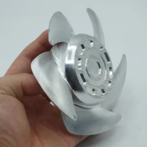
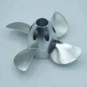
Modern aerospace aluminum brackets rarely feature simple 2.5D planar geometry. They are highly contoured, weight-optimized, topology-generated structures designed to snake through dense airframe assemblies and bypass wire harnesses. Machining these from billet requires simultaneous 5-axis interpolation to reach every undercut, compound angle, and internal pocket without removing the part from the fixture.
JXD Machining deploys Taikan 5-axis machining centers (such as the V-400U and V-500U series) equipped with high-precision direct-drive rotary tables and original imported Siemens 5-axis CNC systems. These machines execute dynamic swarf milling, where the side of the end mill stays in continuous contact with a constantly twisting surface contour. By keeping the tool vector perfectly normal to the surface, the machine avoids the microscopic “stair-stepping” effect that plagues 3-axis ball-mill surfacing. This 5-axis capability produces a flawless surface finish measuring Ra 0.4μm straight off the machine tool.
The ability to machine five sides of a billet component in a single setup mathematically eliminates the tolerance stacking errors that occur when a casting must be flipped and re-indicated across three separate fixtures. True position and concentricity callouts between opposing bores are held effortlessly because the part never leaves the zero point of the machine’s coordinate system.
The Ultimate Showdown: Billet vs. Cast Properties
To definitively illustrate the physical superiority of billet for high-stress applications, mechanical designers must look at the raw metallurgical data. The following table compares Billet 6061-T6, the standard workhorse of aerospace machining, against A356-T6, the most common premium cast aluminum alloy.
| Mülk | Billet 6061-T6 | Typical Cast A356-T6 |
| Akma Dayanımı (MPa) | 240 – 290 | 170 – 200 |
| Ultimate Tensile Strength (MPa) | 260 – 310 | 240 – 270 |
| Fatigue Strength (MPa) | 96 | 50 – 75 |
| Kırılma Uzaması (%) | 10% – 12% | 3% – 6% |
| Sertlik (Brinell) | 93 – 95 HB | 75 – 80 HB |
| Machinability (CNC Milling) | Excellent: High MRR, predictable chip formation, extended tool life. | Poor: Abrasive Si particles cause severe tool chipping and rapid wear. |
| Anodizing Quality | Excellent: Uniform Type III hardcoat, rich and consistent dye absorption. | Poor: Silicon smutting, acid bleed-out from pores, severe color mismatch. |
| Upfront Setup Costs | $0 (Direct from CAD to CAM to Machine) | $10,000 – $50,000+ (Steel die molds or sand patterns) |
Data aggregated from standard metallurgical references and physical testing.
The data dictates the engineering reality. Billet 6061-T6 offers nearly double the fatigue strength of cast A356-T6 (96 MPa vs. 50-75 MPa). When an aerospace bracket undergoes cyclic vibrational loading from a jet turbine, that 40 MPa delta is the sole factor preventing a mid-air structural failure. The casting’s fatigue limit is artificially depressed by the statistical certainty of internal gas voids.
Additionally, the elongation percentage—a direct measure of material ductility—is twice as high in the billet alloy (10% vs 3.8%). If a sudden shock load exceeds the yield strength, a billet part will bend and deform, absorbing the kinetic energy. A cast part, severely lacking ductility due to its coarse grain structure, intermetallic phases, and internal porosity, will simply snap and separate. The Brinell hardness values (93 HB vs 75 HB) further confirm that the billet material provides superior resistance to surface indentation and localized bearing loads.
DFM Tip: When Does Billet Become Cheaper Than Cast?
A pervasive and highly destructive cognitive bias exists among engineering procurement teams: the assumption that casting is inherently cheaper than CNC machining. Buyers look at an initial quote showing a die-cast part at $9.20 per unit and a machined billet part at $35.00 per unit, and immediately select the casting. This superficial analysis ignores the Total Cost of Ownership (TCO) and completely fails to account for the break-even volume dynamics of manufacturing.
Casting is an entirely tooling-dependent process. High-pressure die casting requires complex molds cut from hardened H13 tool steel, featuring precision water cooling channels, ejector pin arrays, and mechanical side-action slides for undercuts. The initial capital expenditure for this tooling ranges from $10,000 to over $50,000. Sand casting tooling is cheaper ($500 to $5,000) but results in a terrible surface finish that requires heavy, expensive secondary machining anyway.
If your project requires 50 to 500 units—the exact production volume of most low-earth-orbit satellites, specialized drones, surgical robots, and performance automotive builds—billet machining is mathematically cheaper. Amortizing a $30,000 mold over 300 parts immediately adds $100 to the cost of every single casting. The true break-even point where die casting finally becomes more economical than CNC milling typically falls between 500 and 5,000 units, heavily dependent on the part’s geometric complexity.
CNC machining requires zero tooling investment. An engineer outputs a STEP file, the CAM programmer generates the G-code, a vise is clamped to the Haas VF-4SS table, the Renishaw probe sets the work offsets, and production begins immediately. Lead times drop from 8 weeks for mold fabrication down to 1-2 weeks for machined billet delivery.
Furthermore, castings are never truly finished when they eject from the mold. Critical mating surfaces, bearing bores, and O-ring grooves must still be placed on a CNC machine to hit aerospace tolerances. Therefore, the buyer ends up paying for the expensive casting tool, the foundry casting process, ve a secondary CNC machining operation. Hogging the entire part out of billet merges all of these steps into one highly controlled environment, slashing logistical overhead.
Quality Assurance and CNC Machining Aluminum Tolerances
The economic argument for billet strengthens exponentially when accounting for the Cost of Poor Quality (COPQ). Castings suffer from highly variable yield rates. A batch of 100 castings might contain 15 units with internal voids that are only discovered during final machining. When the cutting tool exposes a hidden pore on a critical sealing face, that part is scrapped. You have now paid for the casting, the shipping, and the machining time, only to throw the aluminum in the recycling bin.
Machining straight from solid billet allows elite machine shops to guarantee a 100% first-article pass rate. JXD Machining operates under strict IATF 16949 and ISO 9001 quality management systems, which demand total process control and material traceability from the raw billet mill certificate to the finished part. Hitting tight CNC machining aluminum tolerances requires rigorous metrology validation.
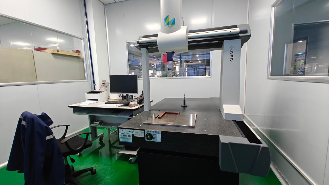
To prove these tolerances, the shop floor relies on Hexagon Coordinate Measuring Machines (CMM). When an aerospace bracket requires a bearing bore with a diametric tolerance of ±0.005mm and a concentricity callout of 0.01mm to a datum axis, a manual micrometer is insufficient. The Hexagon CMM utilizes ultra-sensitive tactile scanning probes to map the internal geometry of the machined feature, comparing millions of data points directly against the original 3D CAD model.
Surface profilometers physically drag a diamond stylus across the machined faces to guarantee the Ra 0.4μm finish required for high-pressure hydraulic sealing faces. Because billet material does not contain the hard silicon spots, intermetallic phases, or microscopic voids of cast material, the tool pressure remains perfectly constant during the final finishing pass. This constant tool pressure ensures that the CMM inspection report shows green across all Geometric Dimensioning and Tolerancing (GD&T) callouts. We document everything—from raw material certs to inspection reports—so OEMs can audit quality at any step, a mandatory requirement for AS9100 and IATF 16949 compliance.
Sonuç
The engineering consensus on the shop floor is absolute: for components subjected to cyclic fatigue loading, high-frequency vibration, or extreme fluid pressures, casting is an unacceptable risk. The micro-porosity inherent in the solidification of A356 aluminum acts as a breeding ground for stress risers and crack initiation. The abrasive silicon inclusions destroy cutting tools, strip tapped threads, and the porous surface violently rejects Type III hardcoat anodizing, leading to acid bleed-out and cosmetic failure.
Billet aluminum alloys like 6061-T6 and 7075-T6 deliver continuous grain flow, double the fatigue strength, and flawless machinability. Utilizing the sheer horsepower, rigidity, and speed of 12,000 RPM spindles on Haas and Taikan 5-axis machines, the material removal rates of modern CNC milling have completely negated the old volume-cost arguments of foundries for low-to-medium production runs. Machining from solid billet guarantees tight tolerances, perfect surface finishes, and zero hidden defects.
Stop risking your mission-critical assemblies on porous castings. Upload your STEP/IGS files to JXD Machining’s engineering team today for a free DFM review and let’s discuss machining it from solid billet.