
Copper is the material engineers reach for when a part has to move current, move heat, or do both at the same time. Its electrical conductivity is second only to silver, its thermal conductivity is roughly ten times that of steel, and it machines cleanly enough to hold tight tolerances on a production CNC machine. This guide covers the grades we machine most often, the cutting parameters that keep conductivity intact, and the practical steps for holding ±0.01 mm on copper parts for electronics and busbars.
The catch is that copper is soft and gummy. It work-hardens slowly, it grabs tooling, and it distorts easily under clamping or cutting heat. Every decision in a copper process plan is really a decision about how to remove material without damaging the two properties the customer is paying for: conductivity and dimensional stability.
Why Copper Is Specified for Electrical and Thermal Duty
Copper sits at the top of the conductivity table for practical engineering metals. Measured against the International Annealed Copper Standard (IACS), commercial pure copper is the 100% reference point, and only silver conducts better. That is why busbars, terminals, RF cavities, and high-current contacts are almost always copper.
The same free-electron structure that carries current also carries heat, so copper doubles as a thermal conductor. Components that have to dump heat — heat sinks, cold plates, induction coils, and power-electronics spreaders — use copper for the same reason they use it for current. If you need both functions in one part, copper is usually the only sensible answer. JXD machines these parts for the electronics industry as well as for custom heat sinks and thermal-management hardware.
Copper Grades for CNC Machining: C11000 vs C10100
Two grades account for most precision copper work. C11000 (electrolytic tough pitch, ETP) is the everyday choice, and C10100 (oxygen-free electronic, OFE) is specified when oxygen content matters. The difference is not cosmetic — it changes both conductivity and how the part behaves in a hydrogen or vacuum environment.
| Propriedade | C11000 (ETP) | C10100 (OFE) |
|---|---|---|
| Copper content | ≥99.90% | ≥99.99% |
| Oxygen content | 0.02–0.05% | ≤0.0005% |
| Electrical conductivity (% IACS) | 100–101% | 101–102% |
| Thermal conductivity (W/m·K) | 388–391 | 393–397 |
| Typical hardness (annealed, HV) | 45–55 | 45–55 |
| Relative machinability | Good, gummy | Good, gummy |
| Typical use | Busbars, terminals, general conductors | Vacuum, RF, hydrogen-fired, high-purity electronics |
If a part will be brazed, welded, or run in a reducing atmosphere, choose C10100. ETP copper contains oxygen that can react at grain boundaries during high-temperature processing and cause embrittlement, so OFE is the safe specification for those processes.
Machinability of Common Copper Alloys
Pure copper and its alloys machine very differently. Free-machining brass is easy; pure copper is not. The table below summarizes the relative behavior of the grades we see most, so a designer can anticipate cycle time and surface finish before quoting.
| Liga | Family | Maquinabilidade | Notes |
|---|---|---|---|
| C11000 | Pure copper (ETP) | Fair | Gummy, builds edge on tool, needs sharp positive tooling |
| C10100 | Pure copper (OFE) | Fair | Same behavior as C11000, better purity |
| C14500 | Tellurium copper | Bom | Free-machining, retains ~93% IACS conductivity |
| C26000 | Cartridge brass | Excelente | Best chip formation, poor thermal/electrical conductivity vs pure copper |
| C36000 | Free-cutting brass | Excelente | Benchmark for machinability, not a conductor |
| C93200 | Tin bronze | Bom | Bearing-grade, lower conductivity |
The rule of thumb: as conductivity rises, machinability falls. Tellurium copper is the compromise when a part needs both reasonable chip control and high conductivity. You can compare these against other conductor and structural options on our copper material page and the broader material selection guide.
Machining Parameters That Protect Conductivity
Copper’s conductivity is a function of its chemistry and its internal structure. Cold work raises strength but also raises electrical resistance, and excessive heat can anneal or oxidize the surface. The process parameters below keep the material in its best conductive state.
- Tooling: use sharp, polished carbide with a high positive rake and a generous clearance angle. Coated tools (TiN, TiAlN) resist the built-up edge that plagues pure copper.
- Cutting speed: 200–400 m/min for carbide turning of pure copper; lower if the machine is light or the part is thin-wall.
- Feed and depth: keep a positive feed per tooth so the tool cuts rather than rubs. Rubbing work-hardens the surface and raises local resistance.
- Coolant: flood coolant or high-pressure through-tool coolant to carry heat away. Pure copper conducts heat into the part and the fixture fast, so thermal growth is a real tolerance risk.
- Finishing passes: take a light finishing cut with a fresh edge to minimize cold work in the functional current-carrying surfaces.
Surface condition matters too. A clean, low-roughness machined surface lowers contact resistance at joints and improves bonding for plated or soldered interfaces. Our surface finish guide covers the finishes that suit conductive copper parts.
Holding ±0.01 mm Tolerances on Soft Copper
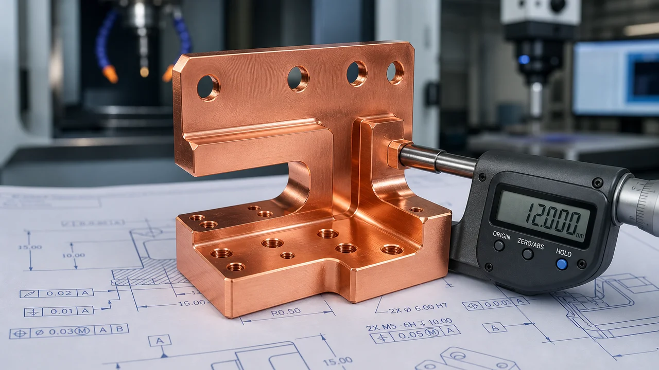
Copper’s low rigidity and high thermal expansion are the two reasons it is difficult to hold tight tolerances. Free machining aluminum forgives a heavy clamp; copper does not. To reach ±0.01 mm reliably, the process has to control the whole environment, not just the cut.
- Thermal control: let the blank and the machine reach equilibrium before finishing. Copper expands roughly 16.5 µm/m·°C, so a 5 °C swing across a 200 mm part moves it more than 15 µm.
- Gentle fixturing: use soft jaws machined to the part profile, vacuum chucks, or light mechanical clamping. Point-loading a soft copper wall distorts it before the tool ever touches it.
- Rough and finish separately: rough heavy, then stress-relieve or allow the part to settle, then take finishing cuts with minimal stock. This removes the residual stress that would otherwise move the part after unclamping.
- In-process probing or CMM verification: verify critical features on the machine or on a CMM rather than trusting the tool offset alone.
- Sharp, on-size tooling: tool wear on gummy copper is fast; change or inspect edges before the finishing pass.
These techniques are the same ones behind our micro copper part machining work and our general CNC machining tolerances guide. When a drawing specifies ±0.01 mm, tell us which features are functional — selective tolerancing keeps cost down without compromising current-carrying performance.
Typical Copper CNC Machined Components
- Busbars and laminations for power distribution, inverters, and battery packs.
- Terminals, contacts, and connector pins where low contact resistance is critical.
- Heat sinks, cold plates, and vapor-chamber bases for power electronics and LED systems.
- RF and microwave components such as waveguides, cavities, and antenna elements.
- Induction coils and electrode parts that combine high current with high heat.
- Precision shims, spacers, and sealing rings used inside electrical assemblies.
Working With JXD on Copper Parts
JXD machines pure copper, tellurium copper, brass, and bronze to production tolerances with full inspection documentation. Because copper parts are usually electrically or thermally functional, we treat conductivity and dimensional stability as first-class requirements rather than secondary checks. Send a drawing or STEP file with your critical features and expected current or thermal load, and our engineers will recommend the grade, the process, and the tolerance plan that gets the part right the first time. Start with our contact page to request a quote.
 Portuguese
  English
  German
  Italian
  Russian
  Spanish
  Turkish
  French