Sourcing custom precision components from global suppliers often introduces significant supply chain risks for procurement professionals. Stories of material substitutions—such as commercial-grade aluminum being used instead of certified aerospace-grade alloys—are common in the manufacturing sector.
A single batch of out-of-specification raw material can lead to premature stress cracking, assembly misalignment, or catastrophic field failures, rendering months of engineering work completely useless.
In high-precision manufacturing, superficial claims of quality hold no value. True reliability is built entirely on empirical data, certified traceability, and strict adherence to international standard operating procedures.
At the JXD Machining facility, quality assurance is treated as an unbroken, documented chain of custody from the initial foundry melt to the final dimensional inspection. This technical analysis demonstrates how a structured precision machining QA framework eliminates risk and establishes absolute verification.
Material Traceability: No Room for Fake Alloys
Material tracking must begin the moment raw stock arrives at the receiving bay. Every shipment of metal must be accompanied by an authentic Material Certificate, also known as a Mill Test Report (MTR).
This quality assurance document serves as a metallurgical birth certificate, detailing physical and chemical properties as certified by the producing mill.
| MTR Key Parameters | Technical Metric & Standards | Operational Significance |
| Material Heat Number |
Unique furnace batch code |
Provides a traceable link back to the specific molten batch. |
| Chemical Composition |
Exact percentages of elements (C, Cr, Ni, Mo, Si) |
Determines critical physical characteristics like corrosion resistance. |
| Propriétés mécaniques |
Yield strength, tensile strength, elongation, hardness |
Establishes load-bearing capacity and structural fatigue limits. |
| Specifications Met |
Compliance with ASTM, ASME, or SAE standards |
Confirms structural fitness for regulated industrial applications. |
The structure of a Material Heat Number provides a systematic method for tracking the metallurgical melt. Typically, the first digit corresponds to the furnace number, the second denotes the melt year, and the final digits represent the specific melt batch number. This coding system provides traceable links from foundry to finished goods.
However, treating an MTR as an infallible guarantee represents a high-risk operational strategy known as the “Paper Tiger” problem. Documentation can easily be separated from physical inventory, and human errors during transit can lead to material mix-ups where substandard stock inherits valid paperwork.
For example, a spool of weld wire can be physically labeled as 316L, matching its packaging and MTR, yet contain Grade 308 wire. If used in corrosive environments, this error causes premature corrosion and latent mechanical failure.
To eliminate the Paper Tiger risk, the JXD Machining quality team establishes an immediate firewall at receiving using Positive Material Identification (PMI). Using handheld X-ray Fluorescence (XRF) spectrometers like the Niton XL2 GOLDD, the quality team performs non-destructive chemical analysis directly on the physical metal bars to verify their chemical composition before they are booked into inventory.
           │
           ▼
 ──► Validate Heat Number matches Material Tags
           │
           ▼
 ──► XRF Chemical Analysis via Niton XL2 GOLDD
           │
           ▼
 ──► Generate unique internal ID bar code linked to digital MTR
           │
           ▼
[CNC Machine Loading] ──► Unbroken, flow-down traceability throughout machining
Once verified, each raw material lot undergoes digital twinning at receiving, receiving a unique internal barcode and ID tag to link the physical material to its digital MTR. This ensures unbroken, flow-down traceability through every stage of CNC machining.
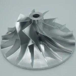
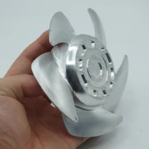
This rigorous screening guarantees that only certified solid bar stock—such as medical-grade titanium (Ti-6Al-4V ELI) or aerospace-grade aluminum (Al 7075-T6)—is loaded onto the CNC machines. The contrast between certified solid stock and cheap, recycled scrap is stark.
Recycled metal often contains hidden micro-voids, internal structural stress, and irregular concentrations of trace elements. During high-speed machining, these defects cause rapid cutting tool chipping, localized thermal warping, and unpredictable dimensional drift. For the end user, utilizing parts machined from recycled scrap results in premature stress fatigue and shortened operational lifespans.
Hexagon CMM: The Final Judge on the Shop Floor
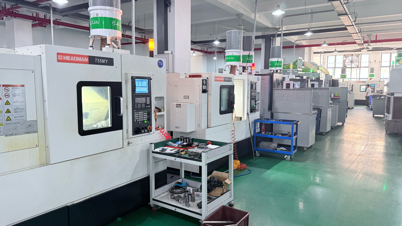
To guarantee dimensional compliance of complex 5-axis geometries, JXD Machining utilizes a high-precision Hexagon CMM running PC-DMIS metrology software.
The Coordinate Measuring Machine (CMM) uses physical touch probes, scanning sensors, and advanced alignment algorithms to establish spatial coordinate datums, comparing physical features directly to the nominal values in the engineering CAD model.
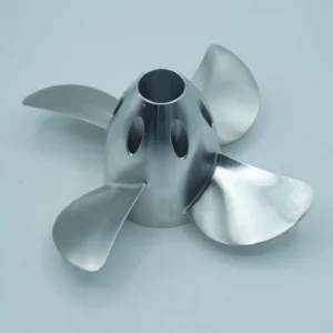
For intricate aerospace components (e.g., blisks, blades, complex manifolds), advanced 4-axis continuous scanning with rotary tables is deployed. This minimizes manual part re-fixturing and probe adjustments, maintaining high throughput and minimizing error.
| Metrology Feature | Manual Metrology Tools (Calipers / Micrometers) | Hexagon CMM with PC-DMIS Integration |
| GD&T Evaluation | Highly limited; cannot verify complex profile tolerances. |
Automatic GD&T application and evaluation directly from CAD. |
| Tolerance Limits | Typically limited to $\pm 0.02\text{ mm}$ with human bias. | Confirms dimensions down to $\pm 0.005\text{ mm}$ with high repeatability. |
| Deep Cavities & Blind Holes | Prone to error due to physical access constraints. |
Executes precise vector-based probe paths with collision detection. |
| Organic Curvatures | Highly subjective; relies on manual point sampling. |
Continuous multi-point scans creating highly accurate digital surfaces. |
To process these massive metrology datasets without system failure or display lag, JXD Machining uses high-performance industrial workstations. These systems are equipped with 64 GB of ECC RAM, Intel Xeon multi-core processors, high-speed NVMe SSDs, and dedicated NVIDIA Quadro GPUs to handle the complex graphical tessellation of large CAD models within PC-DMIS.
By utilizing a Direct CAD Interface (DCI), PC-DMIS extracts design data directly from native CAD files. This completely eliminates human transcription errors and ensures that even the tightest manufacturing tolerances of $\pm 0.005\text{ mm}$ are met, preventing out-of-tolerance components from ever exiting the facility.
AS9102 FAI: The Ultimate Standard for Medical & Aerospace
For critical sectors like aerospace, defense, and medical devices, dimensional accuracy must be supported by formal documentation. The globally recognized standard for verifying first-run manufacturing compliance is the AS9102 First Article Inspection (FAI).
The FAI process serves as empirical proof that all production plans, machine programming, tooling, and inspection protocols can produce a fully conforming part.
An AS9102 FAI Report is composed of three mandatory forms, supplemented by a ballooned drawing :
-
Form 1 (Part Number Accountability): Identifies the FAI part, drawing revision levels, associated sub-assemblies, and serial numbers.
-
Form 2 (Product Accountability): Logs all raw materials, special processes (such as anodizing, passivation, or heat treatment), and functional tests defined by the design requirements.
-
Form 3 (Characteristic Accountability): Records the actual physical measurement or verification of every single design characteristic on the drawing, including linear dimensions, tolerances, surface finishes, and drawing notes.
| AS9102 Form Type | Primary Data Fields Required | Verification Purpose & Traceability |
| Form 1: Part Number |
Part name, revision, serial, and FAIR identifier. |
Establishes the baseline identity of the manufactured component. |
| Form 2: Product |
Material spec, special process codes, functional tests. |
Ties the material certificate and heat code directly to the part. |
| Form 3: Characteristic |
Balloon number, drawing zone, nominal limits, actuals. |
Documents the actual physical measurements of all design features. |
The ballooned drawing acts as the foundational link for Form 3. Quality engineers use specialized software to assign a unique, numbered bubble to every single dimension, note, and GD&T callout on the technical print.
Each numbered balloon corresponds directly to its respective row on AS9102 Form 3. The inspector records the nominal range, the actual measurement taken by the CMM or calibrated hand tool, and the ID of the specific inspection instrument.
This creates a clear, searchable map for the customer, allowing immediate verification of every nominal limit against the actual measured value, such as a precision bore tolerance of $+0.005 / -0.000\text{ mm}$ or a critical surface finish of Ra 0.4μm.
Conclusion and Call to Action
High-precision CNC machining is not merely about shaping metal on a mill; it is about delivering a complete, verifiable chain of custody and robust engineering documentation. Procurement and engineering professionals do not buy parts; they buy structural reliability and peace of mind.
Eliminating risk requires partnering with a facility that treats quality control not as a secondary chore, but as an empirical science.
Global engineering teams are invited to upload their 2D and 3D drawings with demanding tolerances and complex geometries to JXD Machining. The engineering team will review the designs and provide a detailed quotation complete with a tailored quality assurance plan, establishing a rock-solid foundation of trust before a single chip of metal is cut.