The economics of custom aluminum CNC milling are dictated by the physical constraints of subtractive manufacturing and the kinematic limitations of the machine tool. For procurement managers and mechanical engineers in high-precision sectors, the difference between a cost-effective component and a project that exceeds its budget often lies in the nuances of the 3D CAD model. At JXD Machining, the analysis of thousands of projects indicates that design choices made during the early prototyping stages have a compounding effect on final production costs. This report details five specific engineering strategies to optimize custom aluminum parts for manufacturability, focusing on the reduction of machine time, the mitigation of tool wear, and the elimination of high-risk operations.
Standardize Internal Radii and Mitigate Tool Deflection
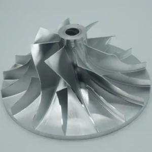
The geometry of the cutting tool is the primary constraint in any milling operation. Because end mills are cylindrical and rotate about a central axis, they are incapable of producing sharp 90-degree internal corners. When a design specifies sharp internal corners, it forces the machinist to move away from standard milling and toward specialized, high-cost processes such as Electrical Discharge Machining (EDM) or manual squaring with broaching tools.
The Technical Logic of the 130% Radius Rule
A frequent error in design is specifying an internal radius that exactly matches the radius of a standard cutting tool. For instance, designing a 5mm radius corner to be cut with a 10mm diameter tool creates a condition where the tool is engaged over a 180-degree arc. This leads to a sudden spike in cutting forces, resulting in significant chatter, poor surface finish, and accelerated tool wear.
The industry standard for optimized custom aluminum CNC milling is to specify an internal radius that is at least 130% of the radius of the cutting tool. This additional 30% margin allows the tool to follow a circular interpolation path, maintaining a consistent chip load and enabling higher feed rates. By allowing the tool to “turn” the corner without coming to a momentary stop, the risk of dwelling—which causes localized heat buildup and work hardening in some alloys—is virtually eliminated.
Quantitative Analysis of Tool Deflection
The physics of tool deflection are governed by the cantilever beam model. The deflection ($\delta$) of an end mill can be approximated by the formula:
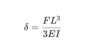
where F is the cutting force, L is the length of the tool overhang, E is the modulus of elasticity of the tool material (typically tungsten carbide), and I is the area moment of inertia. Because L is cubed, even a minor increase in the depth of a cavity requiring a long-reach tool results in an exponential increase in deflection.
When the ratio of cavity depth to corner radius exceeds 3:1, the tool becomes significantly less rigid. In extreme cases, such as the 19:1 ratio identified in ultra-deep cavity case studies, specialized anti-vibration extended insert cutters must be used, which adds considerable machine time and specialized tooling costs to the project.
| Feature Type | Cavity Depth | Recommended Min Radius | Tool Type | Machining Risk |
| Shallow Pocket | < 10 mm | 2.5 mm | Standard 5mm EM | Bajo |
| Standard Cavity | 10 – 30 mm | 5.0 mm | Standard 10mm EM | Bajo |
| Deep Cavity | 30 – 60 mm | 10.0 mm | Long-reach EM | Moderado |
| Ultra-Deep | > 60 mm | > 15.0 mm | Anti-vibration Insert | High |
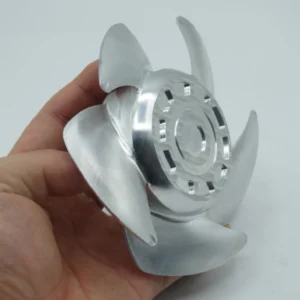
Practical Workarounds: T-Bone and Dog-Bone Undercuts
If a design requires a square component to fit into a milled pocket, the most cost-effective solution is not to minimize the radius, but to use undercuts. T-bone or dog-bone undercuts extend the corner’s shape beyond the functional area, allowing the round tool to clear the corner entirely. This ensures that a square-edged mating part can sit flush against the pocket walls without the need for expensive secondary operations.
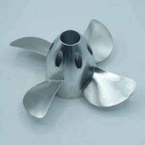
Optimize Wall Thickness for Material Stability
Aluminum alloys, particularly the common Al6061 and Al7075 grades, are prone to deformation during machining due to the release of internal residual stresses and the high temperatures generated at the cutting interface. In the context of machining cost reduction, maintaining adequate wall thickness is critical to preventing part vibration (chatter) and warping.
Minimum Thickness Guidelines for Al6061 and Al7075
While thin walls can be achieved through specialized “mirror milling” or the use of sacrificial support material, these techniques add substantial labor and setup time. For production-ready designs, the following thickness standards apply:
- Aluminio 6061-T6: A minimum wall thickness of 1.5mm is recommended for general applications. While 0.8mm is technically feasible for small, non-structural sections, it often requires slower feed rates to prevent the tool from pushing the material away rather than cutting it.
- Aluminio 7075-T6: Due to its higher strength and hardness, 7075 can theoretically support slightly thinner sections, but it is also more prone to stress-induced warping. Maintaining a 2.0mm minimum for larger 7075 parts is a safer baseline to ensure dimensional stability.
Aspect Ratios and Structural Rigidity
The height-to-thickness ratio is the primary indicator of wall stability. A ratio below 10:1 is generally considered stable for CNC machining. If a wall exceeds this ratio, the frequency of the tool may sync with the resonant frequency of the thin section, leading to severe chatter marks that cannot be removed by finishing passes.
For long, thin sections (over 100mm in length), the risk of bowing is high. In these cases, increasing the minimum wall thickness to 3.0mm or adding structural ribs every 50mm is necessary to maintain flatness.
| Grado de Material | Recommended Min Wall | Absolute Min (Risk) | Height-to-Width Max |
| Al6061-T6 | 1.5 mm | 0.8 mm | 10:1 |
| Al7075-T6 | 2.0 mm | 1.0 mm | 8:1 |
| Al5052 (Softer) | 2.5 mm | 1.5 mm | 6:1 |
Stress Relief and Thermal Management
Aluminum’s high thermal conductivity ($\approx 205 \text{ W/m}\cdot\text{K}$) means that heat from the milling process spreads rapidly throughout the part. In thin-walled elements, this heat can cause thermal expansion during the cut, followed by uneven contraction as the part cools, resulting in a warped final geometry.
To minimize these effects, engineers should specify stress-relieved material, such as 6061-T651, which undergoes a controlled stretching process after heat treatment to neutralize internal stresses. Although this material may carry a 15-20% price premium, the reduction in scrap rates and the elimination of “flattening” operations usually result in a lower total part cost.
Limit Thread Depth to Prevent Tap Failure
In custom aluminum CNC milling, threading is often the highest-risk operation. Taps are delicate tools, and aluminum’s “gummy” nature leads to chip welding and packing, which are the primary causes of tap breakage in blind holes.
The Mechanics of Thread Engagement
A common misconception is that deeper threads provide greater strength. In reality, the first three threads of a fastener carry approximately 75% of the total load. Extending thread depth beyond 2 times the nominal diameter ($2D$) provides negligible mechanical benefit while significantly increasing the likelihood of tool failure.
For aluminum, the optimal thread depth-to-diameter ratio is 1.5x to 2x. Machining a thread to 3x or 4x diameter requires specialized spiral-flute taps to pull chips out of the hole, or thread milling operations which are significantly slower and more expensive than traditional tapping.
Effective Hole Preparation and Clearance
The risk of tap breakage can be reduced from 12% to less than 0.5% through precise hole preparation. For blind holes, it is essential to provide adequate clearance between the end of the thread and the bottom of the pilot hole.
- Drill Depth Clearance: The pilot hole should be at least 1.5 to 2 times the thread pitch deeper than the required full thread depth. This space provides a reservoir for chips to accumulate without being compressed against the bottom of the hole, which causes torque spikes that snap the tap.
- Form Tapping: For ductile aluminum alloys like 6061, thread-forming (roll) taps are highly recommended. These tools displace the material into the thread profile rather than cutting it, producing zero chips and thus eliminating the risk of chip packing.
| Thread Size | Recommended Depth (2D) | Clearance at Bottom | Best Tap Type (Aluminum) |
| M3 x 0.5 | 6.0 mm | +1.5 mm | Form / Roll Tap |
| M6 x 1.0 | 12.0 mm | +3.0 mm | Spiral Flute |
| M10 x 1.5 | 20.0 mm | +4.5 mm | Spiral Flute |
Avoid Unnecessary Tight Tolerances and Metrology Bottlenecks
Tight tolerances are often applied as a “safety factor” by designers, but in custom aluminum CNC milling, they represent the single largest driver of unnecessary cost. Every micron of tolerance tightening below ±0.05mm exponentially increases the manufacturing effort, inspection time, and scrap risk.
The Cost of Precision
A standard 3-axis CNC mill with proper maintenance and thermal control can routinely achieve ±0.05mm tolerances without significant cost penalties. However, tightening this requirement to ±0.005mm can double or triple the machining cost. This increase is driven by:
- Slower Feed Rates: Finishing passes must be made with extremely light depths of cut and slow speeds to maintain dimensional accuracy and surface finish.
- Increased Tool Changes: Tools must be replaced more frequently to account for even minor wear that would be acceptable at looser tolerances.
- Thermal Drift: Because aluminum has a high coefficient of thermal expansion, maintaining ±0.005mm often requires climate-controlled machining environments and in-process probing systems.
Standardizing with ISO 2768
The most effective way to communicate precision requirements while controlling costs is to use general tolerance standards. ISO 2768 provides a framework for linear and angular dimensions, allowing designers to specify a global tolerance class for non-critical features while reserving tight tolerances for functional interfaces.
| Tolerance Level | Numerical Range | Cost Multiplier | Why the Increase? |
| Standard (ISO 2768-m) | ±0.1 mm | 1.0x | Basic setup and inspection. |
| Precisión | ±0.025 mm | 2x – 3x | Extra passes, manual checks. |
| Alta Precisión | ±0.01 mm | 5x | CMM inspection, slow feeds. |
| Extreme | ±0.005 mm | 10x+ | Temperature control, grinding. |
Anodizing Growth and Dimensional Shifts
Aluminum parts are frequently anodized for corrosion resistance or aesthetics. It is a common error to specify tight tolerances without accounting for the thickness added by the anodizing process.
- Type II (Decorative): Adds approximately 5–25 µm total thickness.
- Type III (Hardcoat): Adds 25–100 µm total thickness.
The critical factor is that the oxide layer grows both inward and outward. Generally, 50% of the coating thickness represents “growth” above the original surface. For a precision bore intended for a bearing fit, the pre-machined diameter must be adjusted to account for this growth. Failure to do so results in expensive “over-sized” parts that must be stripped and re-plated, or scrapped entirely.
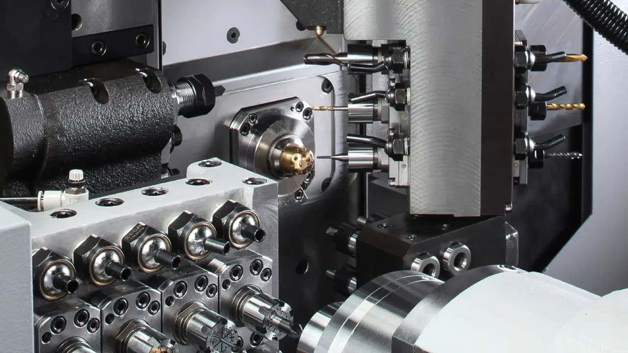
Minimize Machine Setups Through Strategic Part Orientation
The cost of a CNC part is largely determined by the “floor-to-floor” time, which includes the time spent on machine setup and part repositioning. Every time a machinist has to touch the part to flip it or move it to a new fixture, the labor cost increases and the risk of alignment errors (datum shift) rises.
Designing for Single-Setup Access
The most efficient custom aluminum CNC milling involves parts that can be machined from a single orientation. Features like holes, slots, or pockets that are located on multiple faces of a cube force multiple setups.
- Feature Consolidation: If a part requires holes on four sides, evaluate if the design can be modified to place those holes on a single face, or if through-holes can be used to reach both sides from one direction.
- Tool Access Clearance: Designers must ensure that the tool holder will not collide with the part geometry. A rule of thumb is to maintain at least 6mm of clearance around any deep feature to allow for standard tool access.
The Role of 5-Axis Machining
While 5-axis CNC machines have higher hourly rates—often ranging from $100 to $200 per hour compared to $40 to $70 for 3-axis mills—they can significantly reduce the total cost for complex parts. By allowing the tool to access multiple faces in a single setup, 5-axis machining eliminates repositioning labor and reduces the need for multiple expensive fixtures.
However, design simplification should always be the first priority. A part that can be made in two setups on a 3-axis machine will almost always be cheaper than a complex part that requires simultaneous 5-axis movement.
Workholding and “Picture Frame” Strategies
Designing with workholding in mind is essential for cost reduction. Parts with no flat, parallel surfaces are difficult to secure in a standard vise, requiring the creation of custom “soft jaws”.
A more effective strategy for thin or complex parts is “picture frame” machining. The part is designed with a perimeter of sacrificial material that is gripped by the vise or bolted to a sub-plate. All critical features are machined inside this frame, and the frame is removed in a final, simple operation. This approach provides maximum rigidity and prevents the clamping forces from distorting the thin-walled sections of the aluminum part.
Conclusión
Maximizing the efficiency of custom aluminum CNC milling requires a pragmatic understanding of the relationship between geometry, material behavior, and machine kinematics. By standardizing internal radii to 130% of the tool radius and maintaining a 3:1 depth-to-radius ratio, engineers can effectively eliminate tool deflection risks and excessive machine cycles. Furthermore, optimizing wall thickness to a 1.5mm production minimum and restricting thread depths to 2x diameter significantly lowers the risk of structural warping and catastrophic tap failure.
Perhaps most importantly, the strategic use of standard tolerances like ISO 2768 and the minimization of machine setups through intelligent part orientation are the most direct paths to machining cost reduction. At JXD Machining, our goal is to provide transparency and technical expertise to help our clients bridge the gap between complex design and economical production. We encourage you to send your 3D CAD files for a comprehensive DFM (Design for Manufacturing) review and quote to identify potential cost-saving opportunities before production begins.