
A CMM report can show every row as Pass and still leave a buyer with the wrong question answered. If the report uses an obsolete drawing revision, misses a critical datum-based feature, or represents one part without stating the inspection scope, the green status does not prove that the delivered batch matches the purchase requirement.
For CNC parts with tight fits, GD&T callouts, or customer-specified quality records, start with the drawing and the inspection plan. Then use the CMM report to verify that the measured features, datum references, material traceability, and part revision all match the order.

What a CMM report proves — and what it does not
A coordinate measuring machine (CMM) records measured coordinates and evaluates dimensions or GD&T characteristics against the drawing requirement. A report can document size, location, flatness, perpendicularity, profile, or position when the measurement plan and datum structure are defined correctly. ASME Y14.5 provides the design language used for GD&T callouts; the report should preserve the same datum reference frame used on the drawing.
A CMM report does not automatically prove that every part in a shipment was measured. It also does not replace a first article inspection (FAI) package, material test report (MTR), certificate of conformance (CoC), or a customer-specific inspection template. These deliverables answer different questions and should be requested separately when they matter to the application.
| Document or activity | What it is used to verify | What a buyer should confirm |
|---|---|---|
| CMM report | Measured dimensions and specified GD&T features | Drawing revision, balloon numbers, datum references, units, tolerances, and inspection quantity |
| FAI record | Whether the first part from a new or changed setup meets the agreed requirements | Part revision, full feature coverage, inspection scope, and any nonconformance disposition |
| MTR | Material identity and supplied material properties | Material grade, heat or lot traceability where required, and match to the purchase requirement |
| CoC | Supplier statement that the delivered order conforms to specified requirements | Part number, revision, quantity, applicable requirements, and traceability references |
JXD can provide FAI and CMM inspection records, MTR, CoC, and requested quality documents on a project basis. The correct document set depends on the drawing, material, quantity, critical features, and customer requirements confirmed during quotation and technical review.
Read the traceability block before reading the measurements
The first section of a useful report identifies the part, the drawing revision, the material requirement, the inspection date, and the inspected quantity. Compare these items with the purchase order and approved drawing before reviewing any deviation value.
- Part number and revision: The report must match the released drawing revision. A valid measurement against Rev A does not approve a Rev B part if dimensions, GD&T, material, or surface-finish requirements changed.
- Units: Confirm whether the report is in mm or inch. A 0.05 mm tolerance is not interchangeable with ±0.005 in.
- Part and batch identity: When traceability is required, the report should make clear which first article, sample, or production lot it represents.
- Inspection quantity: One inspected part, first-and-last-piece inspection, and 100% inspection are different scopes. The report should not force the buyer to guess which one was used.
- Drawing reference: Balloon numbers or feature IDs should map directly to the drawing. A measurement table that cannot be traced back to a feature is difficult to approve or audit.
This check takes minutes and prevents a common approval error: accepting a well-formatted report that belongs to the wrong revision or does not cover the features that control assembly.
How to read the measurement table
Most CMM reports contain a feature ID, nominal value, actual value, tolerance or limits, deviation, and pass/fail status. The feature ID should match a ballooned dimension on the approved drawing. For GD&T, the table should also identify the characteristic and its datum reference frame.
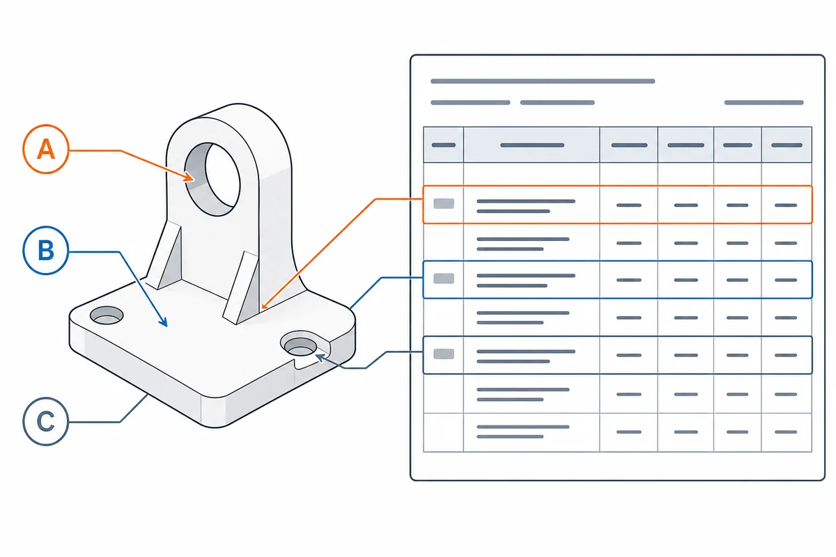
| Report field | Buyer check | Example only |
|---|---|---|
| Nominal | Does it match the drawing value and unit? | 10.00 mm |
| Tolerance or limits | Does it reflect the drawing tolerance, not a substituted general tolerance? | ±0.05 mm |
| Actual | Is the measured result reported for the correct feature? | 10.03 mm |
| Deviation | Does nominal-to-actual arithmetic make sense? | +0.03 mm |
| Status | Is the feature within the specified limits, and is any borderline result explained? | Pass |
In this example, 10.03 mm is inside a 10.00 mm ±0.05 mm limit, so the feature passes. The example is only a reading exercise; it is not a production result. A pass near the limit may still require a discussion when the feature controls a press fit, a seal, a bearing location, or a tolerance stack-up.
Check datum references before approving position or form results
For a hole position, perpendicularity, runout, profile, or flatness callout, the datum setup controls the meaning of the result. A position result cannot be reviewed only by looking at one number. Confirm that the report identifies the same primary, secondary, and tertiary datum sequence shown on the drawing.
For example, a positional tolerance of ⌀0.10 mm relative to datums A, B, and C evaluates the hole location within a cylindrical tolerance zone. If the report evaluates the hole from a different coordinate origin or reverses the datum order, its result may not represent the design intent. Ask for clarification before approving the first article.
Use the same discipline for flatness and profile. Flatness controls a surface without a datum reference; profile and orientation controls usually rely on the datum structure stated in the feature control frame. If the drawing uses GD&T, send the 2D drawing with the RFQ rather than relying only on a STEP file.
CMM inspection and FAI are related, but they are not the same request
CMM inspection is a measurement method. FAI is a first-part verification activity that can include CMM results, visual checks, material documentation, surface-finish confirmation, and customer-required records. A buyer who needs a first article should ask for an FAI package or a defined inspection report, not only “CMM inspection.”
Request FAI when the part is new, the drawing revision changed, the material or surface treatment changed, a new fixture is used, or a critical assembly feature must be verified before a batch proceeds. For a simple prototype, a short list of ballooned critical dimensions may be more useful than an undefined full report. For a high-risk component, define the required records and approval point before material is cut.
Do not specify 100% inspection by default. It can be appropriate for safety-critical, high-value, or especially sensitive features, but it also changes inspection time and cost. State which features require 100% measurement, which can be sampled, and whether a first, last, or random sample is required. The supplier can then evaluate the request against the drawing and production quantity.
Four questions to ask before approving a first article
- Does the report match the released drawing revision? Check the revision, units, material requirement, and every revised ballooned feature.
- Are the functional features actually measured? Focus on mating bores, thread-related dimensions, sealing faces, datum surfaces, position controls, and surfaces with specified Ra requirements. A long report with peripheral dimensions can still miss the feature that drives assembly.
- Is the inspection scope stated? Confirm whether the report represents one first article, a defined sample, or every part. Ask how the sample was selected when batch acceptance is involved.
- Are related documents tied to the same part and lot? Where needed, link the FAI, CMM report, MTR, CoC, surface-treatment documentation, and packaging requirement to the same part number and revision.
These questions turn quality documentation into an approval tool instead of a post-shipment attachment.
What to request in a CNC RFQ when inspection matters
A clear RFQ lets the supplier plan machining, fixturing, inspection, and documentation before the quotation is issued. Send the current 2D PDF and 3D CAD model, then identify which features control function. For a general overview of tolerances, see our CNC machining tolerances guide.
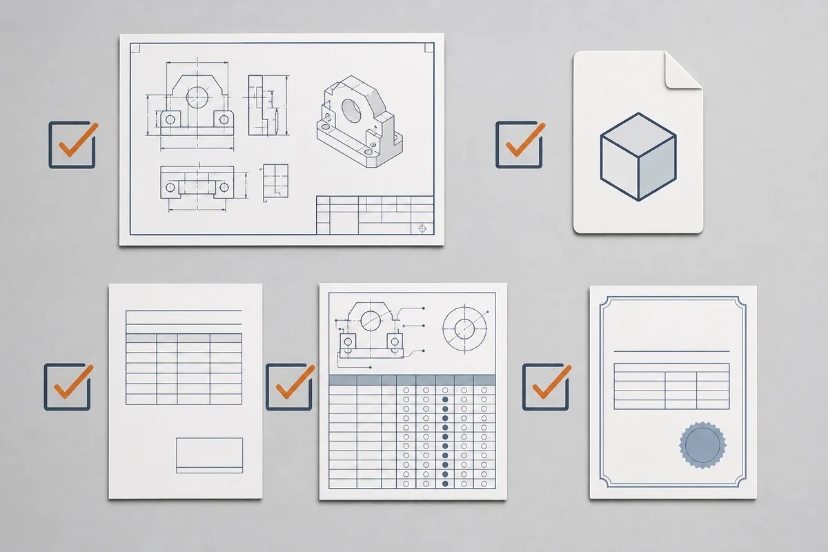
| Include in the RFQ | Why it changes the inspection plan |
|---|---|
| 2D drawing PDF with revision | Defines dimensions, GD&T, datums, surface finish, and balloonable features |
| 3D CAD file | Supports geometry review and measurement-program planning |
| Material grade and condition | Determines material sourcing and whether an MTR is required |
| Critical dimensions and mating features | Prioritizes functional checks such as bores, threads, sealing faces, and locating surfaces |
| Quality-document list | Separates FAI, CMM report, MTR, CoC, and any customer-specific template |
| Quantity and sampling requirement | Defines whether first-piece, in-process, final, sampled, or 100% inspection is needed |
For custom CNC projects, JXD reviews drawings before quotation and can align the requested inspection documents with the part geometry and order requirements. Our quality assurance process explains the broader inspection and document path. If your part includes small turned features, the Swiss CNC machining service page explains when guide-bushing support and turning geometry are relevant.
Use the report to start a technical conversation, not end one
An out-of-tolerance row should be evaluated against function, drawing intent, and disposition requirements. A re-measure may be appropriate if the datum setup, fixture stability, probe path, or feature identification is unclear. A concession, rework, or remake decision should be documented rather than made from a color-coded status alone.
The same applies to a near-limit pass. If a critical bore, shaft, or locating feature consumes most of its ±0.005 mm tolerance on the first article, ask whether the process plan, tool offset strategy, or inspection frequency needs review before production proceeds. The correct action depends on the part geometry, material, quantity, and functional tolerance stack-up.
FAQ
Is a CMM report the same as a first article inspection report?
No. A CMM report records measured dimensions or GD&T characteristics. An FAI package verifies the first part against the agreed requirements and may include CMM data, visual checks, material documentation, and customer-required records.
Which dimensions should be included in a CMM report?
Include dimensions and GD&T features that control function, fit, sealing, alignment, assembly, or customer acceptance. Identify those features in the drawing or RFQ instead of relying on an undefined “full inspection” request.
Do I need a CMM report for every CNC order?
Not always. A simple prototype may need only a short list of critical measurements. New, tight-tolerance, complex, or high-risk parts may need an FAI and a defined CMM report. The inspection level should be agreed during quotation and technical review.
What should I send for a CNC inspection review?
Send the current 2D drawing, 3D model, material grade, critical dimensions, surface-finish requirements, quantity, and requested quality documents. This allows the supplier to review manufacturability and plan the measurement approach before machining starts.
Send the drawing and define the acceptance evidence
Upload the current 2D drawing and 3D model with the material grade, critical features, quantity, and required quality documents. JXD can review the CNC machining and inspection requirements before quotation, then confirm which FAI, CMM, MTR, CoC, or customer-template records are appropriate for the project. For parts in regulated-device programs, see our medical device CNC machining guide for material, tolerance, and validation considerations.
 German
  English
  Italian
  Russian
  Spanish
  Turkish
  French
  Portuguese