
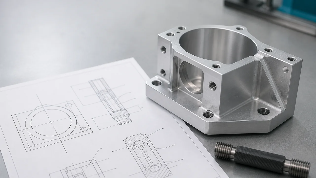
“M6” or “1/4-20” is not a complete manufacturing requirement. A machine shop still needs to know the pitch or thread series, internal thread class, hole condition, required full-thread depth, feature location and acceptance method. If those fields are missing, two suppliers can quote different parts while both believe they followed the drawing.
This guide explains what a buyer should place on the controlled 2D drawing and what should remain a supplier process decision. It is written for custom CNC parts, not for selecting a fastener from a catalog.
What Information Belongs in a Threaded Hole Callout?
A useful callout identifies the finished feature that must be delivered. It does not need to prescribe every toolpath, tap style or machine setting. The table below separates required product information from conditional requirements.
| Field | When it is needed | What it controls | Example format |
|---|---|---|---|
| Thread system and nominal size | Always | Metric or unified-inch family and nominal diameter | M6 or 1/4 |
| Pitch or thread series | Always unless the controlled standard explicitly makes it unambiguous | Axial spacing between thread forms | M6 × 1 or 1/4-20 UNC |
| Internal thread class | When fit and acceptance depend on it | Tolerance class for the internal thread | 6H or 2B |
| Hand | Required for a left-hand thread; right-hand may follow the drawing standard | Direction of engagement | LH |
| Hole condition | Always | Through or blind feature | THRU or BLIND |
| Minimum full-thread depth | For a blind feature or limited threaded extent | Axial length over which complete thread form is required | MIN FULL THREAD DEPTH [X] |
| Total hole depth and end condition | For a blind hole when the remaining geometry matters | Extent of the drilled or machined cavity | HOLE DEPTH [Y] |
| Quantity and pattern identity | For repeated features | Which holes share the requirement | 4X plus a clear leader or pattern note |
| Location and orientation controls | When assembly function depends on them | Where the threaded axis sits relative to datum features | Basic dimensions and an applicable position requirement |
| Finish and masking state | When coating changes final thread condition | Whether the thread is masked, coated or accepted after finishing | A finish note tied to the threaded feature |
| Inspection requirement | When a specific acceptance record is required | Functional thread check, feature location or documented inspection | Defined in the drawing, RFQ or inspection plan |
ISO 261 defines the general plan for ISO metric screw threads, and ISO 965-1 defines a tolerance system for those metric threads. Unified-inch threads use the applicable ASME B1.1 edition specified by the drawing owner or customer. These standards organize thread designations; they do not replace a complete feature callout, depth requirement or inspection scope.
Full-Thread Depth Is Not Total Hole Depth
The required full-thread depth and the total cavity depth control different features. A statement such as “depth 12 mm” is incomplete unless the drawing shows which feature starts where and what the 12 mm applies to.
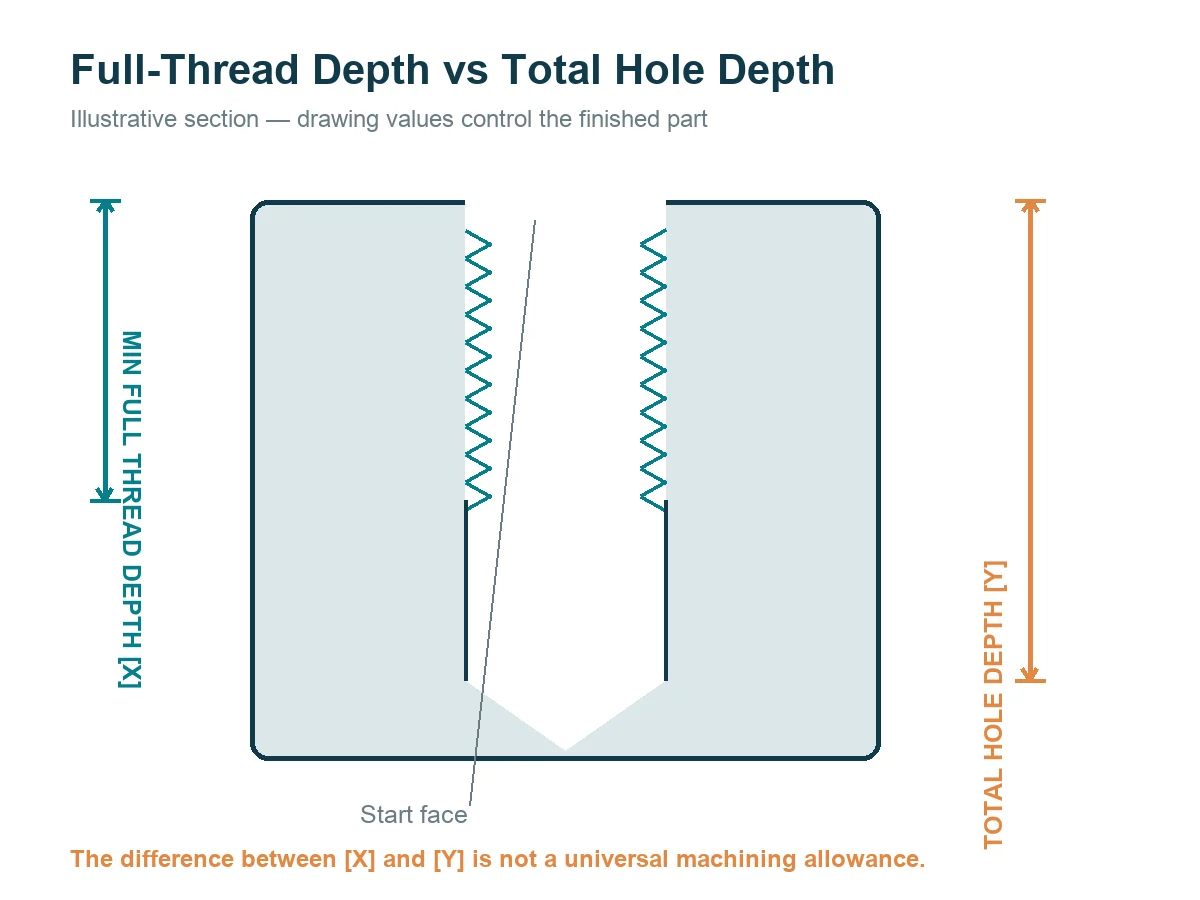
- Full-thread depth defines the minimum axial extent over which the required thread form must be available.
- Total hole depth defines the cavity extent and may include unthreaded clearance, runout and the bottom geometry.
- Start reference identifies the entry face or specified plane from which each depth is measured.
- End condition distinguishes a blind feature, a through cavity and any separately controlled bottom geometry.
A through hole does not automatically require a through thread. A blind hole does not automatically tell the supplier how much full thread is required. The product drawing should define the finished feature; the supplier should then confirm that the selected process can produce it.
How to Read Metric and Unified-Inch Examples
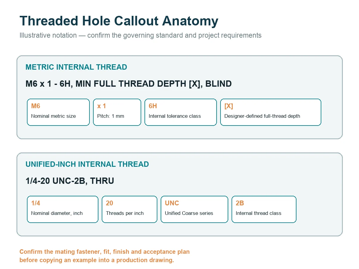
The examples below show notation structure. Bracketed values are placeholders to be completed by the drawing owner; they are not JXD default dimensions.
Metric internal-thread example
M6 × 1 — 6H, MIN FULL THREAD DEPTH [X], BLIND, HOLE DEPTH [Y]
M6identifies the nominal metric thread size.1identifies a 1 mm pitch.6His an internal metric tolerance-class designation.[X]und[Y]must be supplied by the responsible designer.
Unified-inch internal-thread example
1/4-20 UNC-2B, THRU
1/4identifies the nominal diameter in inches.20identifies 20 threads per inch.UNCidentifies the Unified Coarse series.2Bidentifies an internal-thread class.THRUidentifies the stated extent; the section view must still make the affected material clear.
Do not copy either example into a production drawing without checking the mating fastener, governing standard, functional fit, coating state and feature geometry.
Define Position and Orientation Separately from Thread Size
A thread designation controls the thread, not the axis location of the hole. A part can pass a functional thread check and still fail assembly because the threaded axis is misplaced or tilted relative to the mating features.
For a repeated pattern, identify the quantity and the holes to which the note applies. If location is function-critical, define the datum reference framework and applicable location or orientation requirement on the controlled drawing. Avoid relying on an unlabeled 3D model pattern as the only feature-location instruction.
The inspection method should answer the actual requirement. A thread plug gauge can evaluate an applicable functional thread condition, while coordinate measurement may be used for feature location when the setup and evaluation method are suitable. A CMM inspection report does not automatically establish every aspect of thread form or functional fit.
Specify Finish, Masking and the Accepted Process Stage
A thread may be machined before anodizing, plating or another finish, but the accepted condition must match the order requirement. Coating on the flanks can change the final fit. Masking can keep a threaded area uncoated, but that is a product requirement only when the drawing or purchase specification says so.
State whether the thread is accepted before or after finishing and whether the feature must be masked. If a coating specification controls thickness, use that specification and its approved drawing notes. Do not replace the finish specification with a generic note such as “protect all threads.”
For aluminum parts, see JXD’s Type II vs Type III anodizing guide for the distinction between coating systems. The project drawing still controls the specific masking and final-fit requirement.
State How the Thread Will Be Accepted
“Inspect threads” is not a complete procurement instruction. The RFQ and quotation should identify what record or check is required for the delivered parts. The final method depends on the thread requirement, quantity, risk and customer plan.
| Drawing or RFQ requirement | Supplier confirmation before order | Acceptance record |
|---|---|---|
| Thread designation and class | Applicable standard and process are understood | Specified functional thread check or agreed inspection result |
| Minimum full-thread depth | Feature is accessible and process allowance is feasible | Depth evidence defined in the inspection plan |
| Hole position relative to datums | Datum setup and location requirement are understood | Dimensional result tied to drawing revision and feature ID |
| Finish or masking condition | Thread is supplied at the agreed process stage | Visual, dimensional or functional check after the stated finish |
| FAI, CMM report, MTR or CoC | Document scope and any cost are included in the quotation | Document identifies the part number, revision and applicable lot |
At JXD, inspection reports and compliance documents are provided when specified in the RFQ and quotation. The scope should be confirmed before production rather than added after the parts are finished. See our quality inspection and report capabilities.
Five Drawing Mistakes That Delay a CNC Quote
- Writing only “M6” or “1/4-20.” The supplier still lacks the complete series or pitch, class, depth and hole condition.
- Using one unlabeled depth for a blind threaded hole. The buyer and supplier may interpret it as full-thread depth, hole depth or overall feature extent.
- Sending mismatched model and drawing revisions. The 3D model drives geometry and CAM planning; the 2D drawing carries the manufacturing and inspection requirements.
- Leaving quantity, pattern or location ambiguous. A single leader may not make clear whether the callout applies to one hole or every hole in a pattern.
- Adding finish and inspection requirements after quotation. Masking, post-finish fit checks and documentation can change process planning, inspection time and cost.
Copy-Paste RFQ Checklist for Threaded CNC Parts
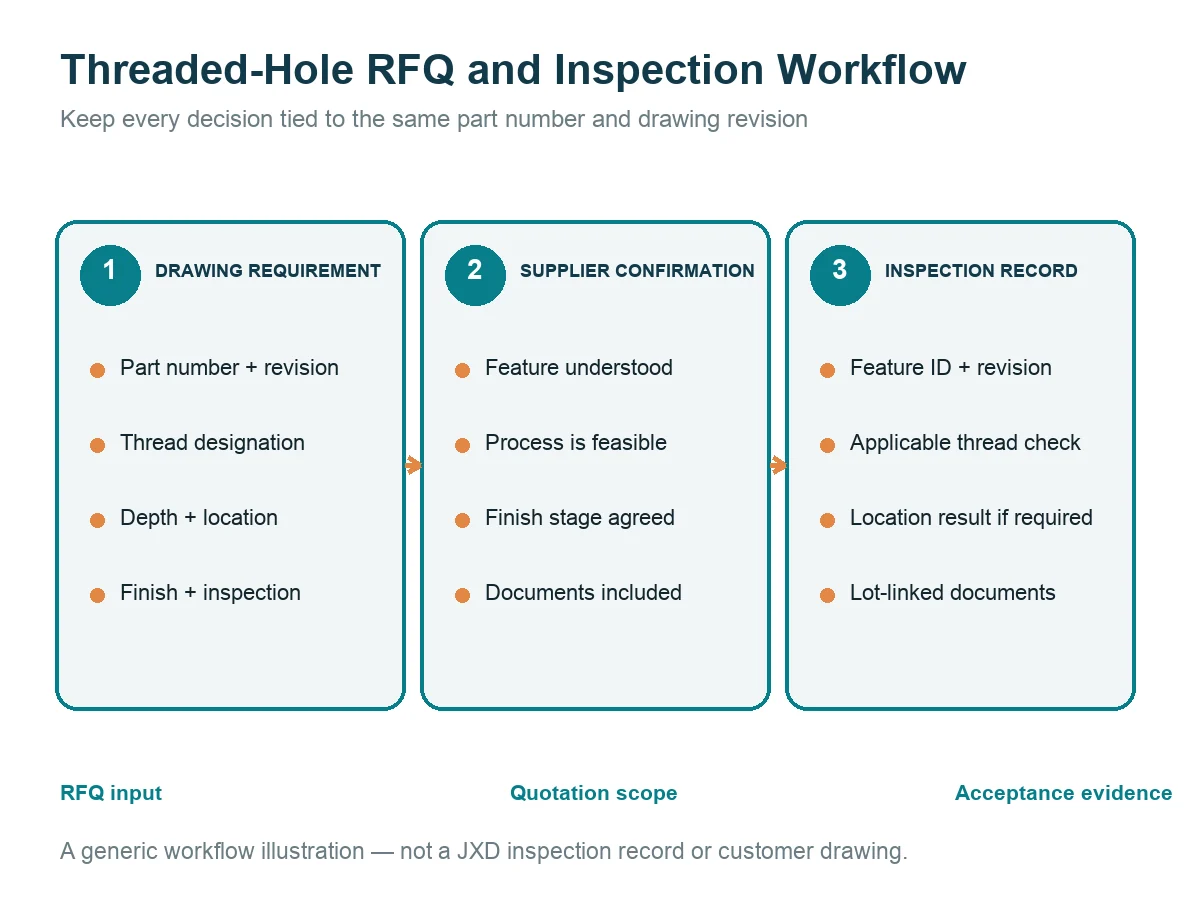
- Part number and drawing revision
- 3D STEP file and controlled 2D PDF drawing
- Material grade, temper or condition
- Complete callout for every unique threaded feature
- Through or blind condition
- Minimum full-thread depth and total hole depth where applicable
- Feature quantity, pattern and location requirements
- Surface finish and masking requirement
- Inspection and document requirements
- Order quantity and requested delivery date
JXD’s threaded-hole manufacturing guide explains tapping and thread-milling options. For a quotation, upload the matching STEP model and 2D drawing through the JXD RFQ page. State the material, quantity, finish and inspection requirements in the same package.
Frequently Asked Questions
Is “M6” a complete threaded-hole callout?
No. It identifies a nominal metric size but does not necessarily define the pitch, internal class, hole condition, required thread depth, quantity, location or inspection requirement.
Is full-thread depth the same as total hole depth?
No. Full-thread depth controls the usable complete thread form. Total hole depth controls the extent of the blind cavity and may include other geometry. The drawing should identify both when both matter.
Does a through hole require a through thread?
Not automatically. “Through hole” describes the cavity condition. The required threaded extent must still be stated or made unambiguous on the controlled drawing.
Should thread geometry be modeled in the STEP file?
The 3D model and 2D drawing must describe the same feature, but a cosmetic or simplified hole representation may not contain every thread requirement. Place the complete thread designation and acceptance requirements on the controlled drawing.
How should a threaded hole be inspected?
Use a method that answers the specified requirement. A functional thread gauge, dimensional measurement, feature-location result or documented first-article check may be appropriate depending on the drawing and inspection plan. Confirm the scope in the RFQ and quotation.
 German
  English
  Italian
  Russian
  Spanish
  Turkish
  French
  Portuguese